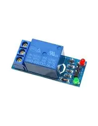
Relay Module Board 1 Channel 5V 10A Low Level Trigger
The 5V 1-Channel Relay Interface Board is an essential component for controlling high-current electrical devices. It is designed for projects involving home automation, industrial automation, robotics, and other control applications. This board allows you to safely manage high-power AC and DC loads using a microcontroller, thanks to its robust relay that can handle up to 10A of current at 250V AC or 30V DC.
Features:
Dual Contact Configuration (NC and NO): The relay offers both Normally Closed (NC) and Normally Open (NO) contacts. When the relay is in the OFF state, the NC contact connects, and the NO contact remains disconnected. When triggered, the NO contact connects and the NC disconnects, allowing for flexible load control.
Microcontroller Compatibility: The relay features a high-impedance controller pin, ensuring safe and efficient interfacing with microcontrollers without excessive current draw.
Power Supply and Status Indicators: The board includes a power indicator to show when the system is powered, and status LEDs provide feedback on the relay’s operation, helping with monitoring and debugging.
Secure Connections: The module includes screw terminals or headers for easy, secure connections to external circuits or devices.
Specifications:
Relay Contacts: One Normally Closed (NC) and One Normally Open (NO)
Control Pin Type: High-Impedance
Power Supply: 5V
Max Load: AC 250V 10A or DC 30V 10A
Indicator LEDs: Power and Status LEDs
Connection Type: Screw terminals or headers
Relay Trigger: Active Low (Relay switches when the input voltage goes below 2.0V)
Working Principle:
Power Supply: Connect a 5V power source to the module, operating within a range of 4.75V to 5.5V.
Trigger Input: A low voltage (0V) at the trigger pin keeps the relay in its default state (NC connected). Applying a high voltage (5V) activates the relay, connecting the NO contact.
Load Control: Depending on the terminal used (NO or NC), the connected load will either be powered on or off when the relay is triggered.
Power and Status LEDs: The power indicator shows when the board is connected to power, and the status LED signals the relay’s on/off state.
Applications:
Home Automation: Control appliances like lights, fans, and HVAC systems remotely.
Industrial Automation: Switch heavy machinery or automated systems with microcontroller commands.
High-Current Load Switching: Suitable for controlling devices that require high-current, such as motors, pumps, or high-power lights.
LED Control: Automate LED lighting setups in series or parallel configurations.
Circuit Example:
Connect the Vcc and GND to the microcontroller.
Trigger the relay by sending a low signal to the IN1 pin.
The load (e.g., light or motor) connects to the NO or NC terminal based on whether you want it to be on or off by default.
Library: No additional library required for operation.
Code Example:
// Pin to control the relay
const int relayPin = 2;

void setup() {
  pinMode(relayPin, OUTPUT);
  digitalWrite(relayPin, HIGH); // Turn off the relay initially
  Serial.begin(9600); // Initialize serial communication
}

void loop() {
  digitalWrite(relayPin, LOW); // Turn the relay ON
  Serial.println("Relay Status: ON");
  delay(1000); // Wait for a second

  digitalWrite(relayPin, HIGH); // Turn the relay OFF
  Serial.println("Relay Status: OFF");
  delay(1000); // Wait for a second
}
Technical Specifications:
Supply Voltage: 3.3V to 5V
Trigger Current: 50-60mA
Relay Max Contact Voltage: AC 250V, DC 30V
Relay Max Current: 10A
Size: 41x16x16mm
Weight: 12g
Comparison (With vs. Without Optocoupler):
With Optocoupler: Provides electrical isolation, protecting the microcontroller from voltage spikes and interference. Best for safety-critical applications.
Without Optocoupler: A more cost-effective option suitable for simple projects where isolation is not a major concern.
Package Includes:
1 x 1-Channel Relay Low Trigger Module
