
Keyestudio UNO R3 Official Upgraded Version KS0172
The Keyestudio UNO R3 KS0172 is an upgraded microcontroller board powered by the ATmega328P. It features enhanced stability, ESD protection, and additional headers. The board provides 14 digital I/O pins, 6 analog inputs, USB communication, and a reset button, making it ideal for robotics, automation, and sensor-based projects. Compatible with the Arduino IDE, it ensures reliable performance through a power jack and supports voltage toggling between 5V and 3.3V.
The Keyestudio UNO R3 KS0172 is a cutting-edge microcontroller development board that empowers you to unlock the full potential of your projects. Meticulously designed for seamless compatibility with the Arduino UNO R3 and the Arduino IDE, the KS0172 incorporates a myriad of features and enhancements, guaranteeing an unparalleled user experience. At the core of this board lies the ATmega328P microcontroller, renowned for its robust processing capabilities that propel your projects to new heights.
Boasting a compact size and an identical form factor to the Arduino UNO R3, the KS0172 seamlessly integrates into your existing framework, ensuring a smooth transition and effortless implementation. The KS0172 revolutionizes power management with its upgraded power circuitry. Equipped with an advanced voltage regulator and reverse polarity protection, this board guarantees a stable and secure power supply for both the board itself and all the devices connected to it. Say goodbye to power-related concerns and embrace uninterrupted creativity.
With 14 digital input/output pins at your disposal, along with 6 analog input pins and 3 Pulse Width Modulation (PWM) pins, you gain unparalleled flexibility in connecting and controlling a wide spectrum of sensors, actuators, and various other components. Your imagination sets the limit.
Convenience and ease of use take center stage with the KS0172. Strategically positioned on the board, the reset button and power LED indicator provide effortless accessibility and real-time monitoring. Furthermore, the built-in In-Circuit Serial Programming (ICSP) header facilitates hassle-free programming using an external programmer, while the onboard USB-to-serial converter (16U2-MU) ensures seamless communication with your computer, enabling swift data transfer and real-time interaction.
The compatibility of the KS0172 transcends the boundaries of the Arduino ecosystem. Embrace the freedom to expand and customize your board's functionality effortlessly with the support it offers for a wide range of shields and modules. Tailor your setup to perfectly align with your project's unique requirements, opening the door to endless possibilities.
Principle of Work:
The Keyestudio UNO R3 KS0172 operates internally by utilizing the ATmega328P microcontroller as its processing unit. This microcontroller executes instructions and manages various functions of the board. It consists of a central processing unit (CPU), memory (such as Flash memory for storing the program code, SRAM for temporary data storage, and EEPROM for non-volatile data storage), and various peripherals for input and output operations.
To program the board, you can connect it to your computer using a USB cable. The KS0172 features a built-in USB-to-serial converter (16U2-MU) that facilitates communication between the board and your computer. When you connect the board to your computer, it appears as a virtual serial port. You can then use the Arduino Integrated Development Environment (IDE) to write and upload your program code onto the board.
The Arduino IDE provides a user-friendly interface for programming the board. It allows you to write code in a simplified version of the C++ programming language and provides a library of functions that make it easier to interact with the board's peripherals and components. Once you have written your code, you can compile it within the IDE and upload it to the KS0172 board via the USB connection.
The KS0172 board includes a reset button that you can press to restart the program execution or to put the board into a programming mode. This reset button is useful when you want to upload a new program or if you want to restart your program's execution.
In addition, the KS0172 has a variety of input and output interfaces. It features 14 digital input/output pins, 6 analog input pins, and 3 PWM pins. These pins allow you to connect and control various sensors, actuators, and other electronic components. You can interface with these pins in your program to read inputs or control outputs as per your project requirements.
Pinout of the Module:
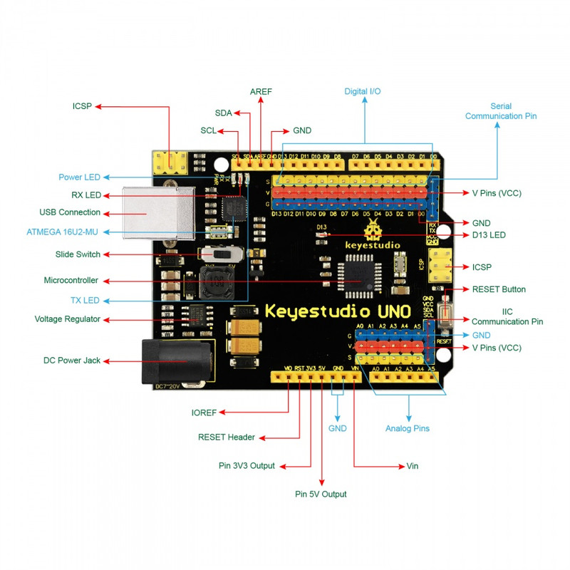
- Power and Basics:
- DC Power Jack
- USB Connection
- Power LED
- Ground (GND)
- Digital I/O:
- 14 Digital I/O Pins
- 6 PWM Pins
- Analog Input:
- 6 Analog Input Pins
- Communication:
- Serial Communication Pin
- IIC Pins (SDA, SCL)
- Programming and Debugging:
- ICSP Header
- RESET Header
- Indicator LEDs:
- D13 LED
- TX and RX LEDs
- Power and Voltage Control:
- V Pins (3.3V / 5V switch)
- Voltage Regulator
- Microcontroller:
- ATmega328P-AU
Applications:
- Robotics
- Home Automation
- Internet of Things (IoT)
- Sensor Applications
- Data Logging and Monitoring
- Interactive Art Projects
- Education and Learning
- Prototyping and DIY Projects
- Automation and Control Systems
- Gaming and Entertainment
Circuit:
We will not need any circuit. In this testing code, we will rely on the built-in LED on the 13th pin.
Connecting with Arduino First Time:
- Install the Arduino IDE
- Connect the Board via USB
- Install Board Drivers (if required)
- Select the Board and Port from Arduino IDE
- Upload a Test Sketch (e.g., Blink)
- Verify the Connection
Code:
// Pin connected to the built-in LED
const int LED_PIN = 13;

void setup() {
  pinMode(LED_PIN, OUTPUT);
  Serial.begin(9600);
  while (!Serial) {
    delay(100);
  }
  Serial.println("Serial Monitor Blink");
}

void loop() {
  digitalWrite(LED_PIN, HIGH);
  Serial.println("LED ON");
  delay(1000);

  digitalWrite(LED_PIN, LOW);
  Serial.println("LED OFF");
  delay(1000);
}
To view the serial monitor output:
- Connect the board via USB
- Open Arduino IDE > Tools > Serial Monitor
- Set baud rate to 9600
You should now see the messages "LED ON" and "LED OFF" printed in the serial monitor while the LED blinks.