
Features:
- 2-channel, dual H-bridge motor driver
- Can control two DC motors or a single stepper motor
- Maximum current rating of 2A per channel
- The maximum voltage of 35V
- Built-in protection against over-current, over-temperature, and over-voltage conditions
- Can be controlled with a variety of microcontrollers
- Provides several input options for controlling the motors
- Built-in voltage regulator for a wide range of input voltages
- On-board 5V power supply for external circuitry or microcontrollers
- Compact design with four screw terminals for connecting motors
- Widely used in robotics, automation, and other DIY projects
- Cost-effective and reliable solution for controlling DC motors and stepper motors.
Principle of Work:
The L298N motor driver module uses a dual H-bridge configuration to control the speed and direction of DC motors or the step sequence of a stepper motor. The H-bridge circuit consists of four transistors that can be controlled by input signals from a microcontroller. The L298N module has two H-bridges, one for each motor channel. The H-bridge allows the current to flow in either direction through the motor, enabling the module to control the motor's speed and direction. The input signals from the microcontroller control the H-bridge transistors to either turn on or off the motor. By varying the on-time and off-time of these transistors, the module can adjust the amount of power supplied to the motor, effectively controlling its speed. By reversing the direction of the current flow in the motor, the module can change the motor's direction of rotation. In addition to the H-bridge circuitry, the L298N motor driver module also includes several built-in protections to prevent damage to the motors and the module. These protections include over-current, over-temperature, and over-voltage protection.
Pinout of the Module:
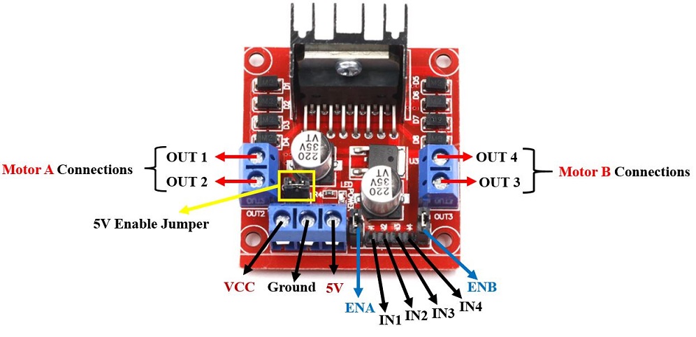
- Enable A - this pin is used to enable or disable channel A of the motor driver. A logic high (5V) will enable the channel and a logic low (0V) will disable it.
- Input 1A - this pin is used to control the direction of rotation of motor A. A logic high will cause the motor to rotate in one direction, while a logic low will cause it to rotate in the other direction.
- Input 2A - this pin is used to control the speed of motor A using pulse-width modulation (PWM). The duty cycle of the PWM signal determines the speed of the motor.
- Output A - this pin is connected to the positive terminal of motor A.
- Ground - this pin is connected to the ground of the system.
- Output B - this pin is connected to the positive terminal of motor B.
- Input 2B - this pin is used to control the speed of motor B using PWM.
- Input 1B - this pin is used to control the direction of rotation of motor B.
- Enable B - this pin is used to enable or disable channel B of the motor driver.
Note that pins 1, 2, and 9 are control pins that are connected to a microcontroller or other control circuitry. Pins 3 and 7 are PWM pins that are also connected to the microcontroller, while pins 4 and 6 are connected to the positive terminals of the motors. Finally, pin 5 is connected to the ground of the system.
Applications:
- Robotics: The L298N motor driver module is widely used in robotics projects for controlling the motion of the robot, including its wheels, arms, and other moving parts.
- Automation: The module can be used in industrial automation systems for controlling conveyor belts, pumps, and other machinery.
- CNC machines: The L298N motor driver module is commonly used in computer numerical control (CNC) machines for controlling the movement of the cutting head.
- Home automation: The module can be used in home automation systems for controlling the opening and closing of doors, windows, and blinds.
- Automotive applications: The module can be used in automotive applications for controlling the speed and direction of motors used in windshield wipers, power windows, and other motorized components.
- Educational projects: The L298N motor driver module is a popular component in educational projects for teaching students about motor control and electronics.
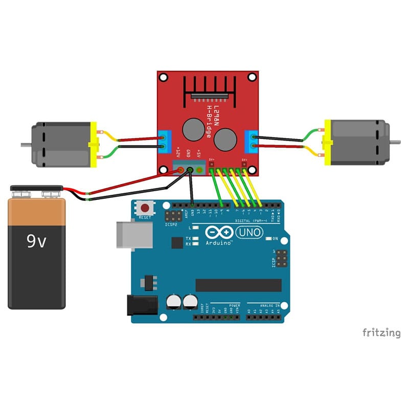
Circuit:
The connections required for the circuit:
- Connect the L298N motor driver module to the Arduino as follows:
- ENA pin to Arduino pin 3
- IN1 pin to Arduino pin 4
- IN2 pin to Arduino pin 5
- ENB pin to Arduino pin 9
- IN3 pin to Arduino pin 6
- IN4 pin to Arduino pin 7
- Connect the common ground (GND) of the L298N motor driver module, Arduino, and power source together.
- Connect a 9V battery to the power input of the L298N motor driver module.
- Connect the ground (GND) of the 9V battery to the common ground (GND) of the L298N motor driver module, Arduino, and power source.
- Connect the DC motors to the output pins of the L298N motor driver module as follows:
- Motor A: Connect the positive (+) wire to the OUT1 pin and the negative (-) wire to the OUT2 pin.
- Motor B: Connect the positive (+) wire to the OUT3 pin and the negative (-) wire to the OUT4 pin.
Note: Make sure to check the polarity of the DC motors and connect them to the correct output pins of the L298N motor driver module to avoid damaging the motors or the module.
Make sure to connect the L298N motor driver module to the correct pins on the Arduino and provide power to the module using a 6-9V power source. Also, connect the common ground of the module, Arduino, and power source together.
Library:
No Library Needed
Code:
This code reads input from the serial monitor and controls the direction and speed of two DC motors connected to the L298N motor driver module. To control the motors, send the following commands through the serial monitor:
- "Aforward": Moves motor A forward
- "Areverse": Moves motor A in reverse
- "Astop": Stops motor A
- "Bforward": Moves motor B forward
- "Breverse": Moves motor B in reverse
- "Bstop": Stops motor B
// Define motor control pins
#define enA 3
#define in1 4
#define in2 5
#define enB 9
#define in3 6
#define in4 7
void setup() {
 // Set motor control pins as outputs
 pinMode(enA, OUTPUT);
 pinMode(in1, OUTPUT);
 pinMode(in2, OUTPUT);
 pinMode(enB, OUTPUT);
 pinMode(in3, OUTPUT);
 pinMode(in4, OUTPUT);
 // Start serial communication
 Serial.begin(9600);
}
void loop() {
 // Read input from serial monitor
 if (Serial.available() > 0) {
 String input = Serial.readString();
 input.trim();
 // Control motor A
 if (input == "Aforward") {
 digitalWrite(in1, HIGH);
 digitalWrite(in2, LOW);
 analogWrite(enA, 255);
 }
 else if (input == "Areverse") {
 digitalWrite(in1, LOW);
 digitalWrite(in2, HIGH);
 analogWrite(enA, 255);
 }
 else if (input == "Astop") {
 digitalWrite(in1, LOW);
 digitalWrite(in2, LOW);
 analogWrite(enA, 0);
 }
 // Control motor B
 else if (input == "Bforward") {
 digitalWrite(in3, HIGH);
 digitalWrite(in4, LOW);
 analogWrite(enB, 255);
 }
 else if (input == "Breverse") {
 digitalWrite(in3, LOW);
 digitalWrite(in4, HIGH);
 analogWrite(enB, 255);
 }
 else if (input == "Bstop") {
 digitalWrite(in3, LOW);
 digitalWrite(in4, LOW);
 analogWrite(enB, 0);
 }
 }
}
Technical Details:
- Dual H-bridge driver module
- Operating voltage: 5V-35V
- Maximum operating current: 2A (per channel)
- Peak current: 3A
- Logic voltage: 5V
- Maximum power consumption: 25W
- Built-in 5V voltage regulator
- Built-in diode protection circuit
- Control signal input level:
- High: 2.3V ≤ Vin ≤ Vss
- Low: -0.3V ≤ Vin ≤ 1.5V
- Dimensions: 43mm x 43mm x 27mm
Resources:
Features:
- 2-channel, dual H-bridge motor driver
- Can control two DC motors or a single stepper motor
- Maximum current rating of 2A per channel
- The maximum voltage of 35V
- Built-in protection against over-current, over-temperature, and over-voltage conditions
- Can be controlled with a variety of microcontrollers
- Provides several input options for controlling the motors
- Built-in voltage regulator for a wide range of input voltages
- On-board 5V power supply for external circuitry or microcontrollers
- Compact design with four screw terminals for connecting motors
- Widely used in robotics, automation, and other DIY projects
- Cost-effective and reliable solution for controlling DC motors and stepper motors.
Principle of Work:
The L298N motor driver module uses a dual H-bridge configuration to control the speed and direction of DC motors or the step sequence of a stepper motor. The H-bridge circuit consists of four transistors that can be controlled by input signals from a microcontroller. The L298N module has two H-bridges, one for each motor channel. The H-bridge allows the current to flow in either direction through the motor, enabling the module to control the motor's speed and direction. The input signals from the microcontroller control the H-bridge transistors to either turn on or off the motor. By varying the on-time and off-time of these transistors, the module can adjust the amount of power supplied to the motor, effectively controlling its speed. By reversing the direction of the current flow in the motor, the module can change the motor's direction of rotation. In addition to the H-bridge circuitry, the L298N motor driver module also includes several built-in protections to prevent damage to the motors and the module. These protections include over-current, over-temperature, and over-voltage protection.
Pinout of the Module:
- Enable A - this pin is used to enable or disable channel A of the motor driver. A logic high (5V) will enable the channel and a logic low (0V) will disable it.
- Input 1A - this pin is used to control the direction of rotation of motor A. A logic high will cause the motor to rotate in one direction, while a logic low will cause it to rotate in the other direction.
- Input 2A - this pin is used to control the speed of motor A using pulse-width modulation (PWM). The duty cycle of the PWM signal determines the speed of the motor.
- Output A - this pin is connected to the positive terminal of motor A.
- Ground - this pin is connected to the ground of the system.
- Output B - this pin is connected to the positive terminal of motor B.
- Input 2B - this pin is used to control the speed of motor B using PWM.
- Input 1B - this pin is used to control the direction of rotation of motor B.
- Enable B - this pin is used to enable or disable channel B of the motor driver.
Note that pins 1, 2, and 9 are control pins that are connected to a microcontroller or other control circuitry. Pins 3 and 7 are PWM pins that are also connected to the microcontroller, while pins 4 and 6 are connected to the positive terminals of the motors. Finally, pin 5 is connected to the ground of the system.
Applications:
- Robotics: The L298N motor driver module is widely used in robotics projects for controlling the motion of the robot, including its wheels, arms, and other moving parts.
- Automation: The module can be used in industrial automation systems for controlling conveyor belts, pumps, and other machinery.
- CNC machines: The L298N motor driver module is commonly used in computer numerical control (CNC) machines for controlling the movement of the cutting head.
- Home automation: The module can be used in home automation systems for controlling the opening and closing of doors, windows, and blinds.
- Automotive applications: The module can be used in automotive applications for controlling the speed and direction of motors used in windshield wipers, power windows, and other motorized components.
- Educational projects: The L298N motor driver module is a popular component in educational projects for teaching students about motor control and electronics.
Circuit:
The connections required for the circuit:
- Connect the L298N motor driver module to the Arduino as follows:
- ENA pin to Arduino pin 3
- IN1 pin to Arduino pin 4
- IN2 pin to Arduino pin 5
- ENB pin to Arduino pin 9
- IN3 pin to Arduino pin 6
- IN4 pin to Arduino pin 7
- Connect the common ground (GND) of the L298N motor driver module, Arduino, and power source together.
- Connect a 9V battery to the power input of the L298N motor driver module.
- Connect the ground (GND) of the 9V battery to the common ground (GND) of the L298N motor driver module, Arduino, and power source.
- Connect the DC motors to the output pins of the L298N motor driver module as follows:
- Motor A: Connect the positive (+) wire to the OUT1 pin and the negative (-) wire to the OUT2 pin.
- Motor B: Connect the positive (+) wire to the OUT3 pin and the negative (-) wire to the OUT4 pin.
Note: Make sure to check the polarity of the DC motors and connect them to the correct output pins of the L298N motor driver module to avoid damaging the motors or the module.
Make sure to connect the L298N motor driver module to the correct pins on the Arduino and provide power to the module using a 6-9V power source. Also, connect the common ground of the module, Arduino, and power source together.
Library:
No Library Needed
Code:
This code reads input from the serial monitor and controls the direction and speed of two DC motors connected to the L298N motor driver module. To control the motors, send the following commands through the serial monitor:
- "Aforward": Moves motor A forward
- "Areverse": Moves motor A in reverse
- "Astop": Stops motor A
- "Bforward": Moves motor B forward
- "Breverse": Moves motor B in reverse
- "Bstop": Stops motor B
// Define motor control pins
#define enA 3
#define in1 4
#define in2 5
#define enB 9
#define in3 6
#define in4 7
void setup() {
 // Set motor control pins as outputs
 pinMode(enA, OUTPUT);
 pinMode(in1, OUTPUT);
 pinMode(in2, OUTPUT);
 pinMode(enB, OUTPUT);
 pinMode(in3, OUTPUT);
 pinMode(in4, OUTPUT);
 // Start serial communication
 Serial.begin(9600);
}
void loop() {
 // Read input from serial monitor
 if (Serial.available() > 0) {
 String input = Serial.readString();
 input.trim();
 // Control motor A
 if (input == "Aforward") {
 digitalWrite(in1, HIGH);
 digitalWrite(in2, LOW);
 analogWrite(enA, 255);
 }
 else if (input == "Areverse") {
 digitalWrite(in1, LOW);
 digitalWrite(in2, HIGH);
 analogWrite(enA, 255);
 }
 else if (input == "Astop") {
 digitalWrite(in1, LOW);
 digitalWrite(in2, LOW);
 analogWrite(enA, 0);
 }
 // Control motor B
 else if (input == "Bforward") {
 digitalWrite(in3, HIGH);
 digitalWrite(in4, LOW);
 analogWrite(enB, 255);
 }
 else if (input == "Breverse") {
 digitalWrite(in3, LOW);
 digitalWrite(in4, HIGH);
 analogWrite(enB, 255);
 }
 else if (input == "Bstop") {
 digitalWrite(in3, LOW);
 digitalWrite(in4, LOW);
 analogWrite(enB, 0);
 }
 }
}
Technical Details:
- Dual H-bridge driver module
- Operating voltage: 5V-35V
- Maximum operating current: 2A (per channel)
- Peak current: 3A
- Logic voltage: 5V
- Maximum power consumption: 25W
- Built-in 5V voltage regulator
- Built-in diode protection circuit
- Control signal input level:
- High: 2.3V ≤ Vin ≤ Vss
- Low: -0.3V ≤ Vin ≤ 1.5V
- Dimensions: 43mm x 43mm x 27mm